Sunday 19 September 2010

19th September 2010 - Wing Struts

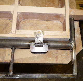
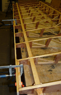
As per advice a small amount of dihedral (0.2 degrees) was introduced to both wings. This is to allow some shrinkage in the struts when the top is welded. Then the wing struts were attached to the fuselage and marked to length with the top level with the centres of the bolt holes in the strut attach brackets. The wing struts were then cut to length and the front and rear edges notched to fit between the brackets. Next sections of douglas fir were cut and planed to fit into the struts. These protect against any possibility of compression failure under negative G loads. Two sections of 1/2" x 0.065" tubing were cut to length the fit between the strut attach brackets and reamed out to take a 3/8" bolt to act as bushings at the top of the strut and then bolted into place. The end of the strut was then flattened to fit neatly against the tubing and the dihedral rechecked. With everything set up as required the struts were then tack welded to the bushing. The temporary wing supports were removed leaving the wings mounted via the three bolts which will hold them in flight. Finally it was all dismantled again. Next job is to final weld the top of the struts.


Posted by Picasa

19th September 2010 - Setting the wing incidence


First today, the fuselage was levelled fore and aft and left to right and chocked in position. Then the wings were bolted into place and the dihedral set to zero as per the plans. All the measuring I'd done http://tailwindbuild.blogspot.com/2009/09/15th-september-2009-rib-rework.html paid off as the front and rear spar spacings exactly matched the fuselage brackets on both sides and the spar attach bolts slid comfortably into place in both the wings. A block was cut to create an exact level between the front and rear spars of the right wing . This wing had both the front and rear spar attach brackets bolted into position so provided the reference for setting the incidence of the left wing. On the left wing the rear spar attach bracket had not been drilled to the spar so the incidence of the left wing could be set precisely the same as the right. This was done and the bracket clamped into position and then drilled through the bushes in the spar and bolted into its final location.

Posted by Picasa

18th September 2010 - Fuselage back from storage

Last week I set to and got the workshop clean and tidy so today I went and collected the fuselage from storage ready to mate the wings. I had intended to do this with the fuselage directly sitting on the drive and chocked up to get it exactly level so that it would be very solid to work on. However, I realised I was going to have to work underneath and that getting it in and out of the workshop was going to need two people so it seemed sensible to get it back on its wheels ready for starting work tomorrow. It hasn't been on wheels since it was primed and it looks much better than before in its smart white coat of paint.
Posted by Picasa

Tuesday 17 August 2010

17th August 2010 - The propeller arrives

A propeller! I managed to find a perfect second hand 69" x 63" Sensenich wooden propeller off a Diamond DA20-C1. This has the correct SAE #1 mounting and 3/8" holes to fit my engine and propeller spacer. The pitch should give my target 150mph cruise at about 2450 rpm. This will be very much a cruise prop so I will have to see how take off distances work out. Worst case it should be possible to rework the prop to reduce the pitch by a couple of inches to improve static rpm.
Posted by Picasa

Thursday 12 August 2010

12th August 2010 - Wing structure complete

The workshop has disappeared under a layer of sawdust and wood shavings again but the wing structures for both wings are now complete and sanded ready for covering. The wingtips have come together well, carrying the profile of the main rib accurately as the wing tapers to the tip. You can just about see in the picture the way in which the top of the main spar stays flat throughout the wingtip but the lower edge tapers up. Next job is a major clean and tidy to create some room as I need to get the fuselage back from storage. I'm going to test mount the wings, finish the struts, and set the wing incidence before covering the wings. This will allow me to make any adjustments necessary as easily as possible. At the moment the rear spar attach bracket is not yet drilled to the spar on the right wing. This will give me a small amount of flexibility to set exactly the incidence of the two wings to be the same. Hopefully, all the measuring I did to make sure the spar spacings exactly match the fuselage will prove to be successful - we will see! It will probably be just into September before the next entry in the blog once I have retrieved the fuselage.
Posted by Picasa

Sunday 8 August 2010

8th August 2010 - Wingtip spar caps and gussets

The construction of the structure of the wings is nearly complete. The wingtip spar caps have been glued in place and the gussets completed for the left wingtip - just the right wingtip gussets to go. Then comes the sanding of the wingtips. The challenge will be to blend the curves together to get smooth surfaces for the wingskins to adhere to.
Posted by Picasa

Friday 6 August 2010

6th August 2010 - Wingtip frames complete

Today I pinned, screwed, and glued the second wingtip frame together. Next job is to fit gussets to strengthen all the joints in the two wingtips and fit spar caps to the main spars and stub rear spars. Then it's back to sanding!
Posted by Picasa

Sunday 25 July 2010

25th July 2010 - Tip ribs cut out

I finished cutting two complete sets of wing tip ribs out of 12mm birch ply today. The picture shows one complete set plus the tip and tail ribs from the second wing. All the cutting was done with the CNC router using a 6.35 (1/4") cutter. The router was programmed for a 8m cut width so the machine does two passes at each height this ensures that the cut to final size is small and means that the finish and accuracy is superb. The program is set to leave 2.5mm thick holding tabs to hold the parts in place as the cut completes. It looks just like a model aeroplane kit (only bigger!) and removing the pieces is easy using a miniature saw blade in the Dremel. I've uploaded the coordinates of the ribs to the Yahoo Tailwind Group site if they are of use to anyone.
Posted by Picasa

Sunday 18 July 2010

18th July 2010 - Wingtip test fit

First job today was to calculate the dimensions for a stub rib rear section which forms the rear inside edge of the wingtip (top right of the picture). This is positioned 1" outboard from the last main rib to allow the aileron mass balance to fit between it and the wingtip to streamline it in normal flight. As before the dimensions for the stub rib were fed in the the CAD/CAM package and a test piece cut out on the router. Then it and the three tip ribs were located on the spars in their correct positions. A blank for the trailing edge was made by sawing along the diagonal of a 2" x 1" section of spruce to make two triangular sections. When angled at 45 degrees along the line of the wingtip trailing edge this section matches the wing section nicely and will need relatively little finish sanding. The ends of the trailing edge were cut to 45 degrees and the outer end pinned to the tip rib. Then the trailing edges of the two intermediate ribs and the stub rib were carefully marked and cut at the required angle. A piece of 3/8" spruce was cut to form the leading edge and the front of the ribs bevelled to match. The picture shows the wing tip assembled on the spars with just one panel pin in the tip rib the only thing holding it together.

Next job is to procure some 15mm birch ply, cut the final ribs for both wings, buy some Aerodux glue and then assemble and glue the two wingtips.
Posted by Picasa

16th July 2010 - Wing tip ribs

I've decided to make the wingtips from wood and have discussed and agreed this with my inspector. The plans do not give any information about the wing section as it tapers from the standard rib to the tip so I started by measuring the distance between the chord line of the main rib and the top and bottom at 10mm stations all along the profile. This was then input to a spreadsheet on the computer. Then I decided on the depth of the tip rib (determined by the height of the strobe/navigation light unit I've got to fit). The length of of the tip rib is given on the plans, together with the spar position in the rib. This allowed me to calculate length and depth of the two intermediate ribs. The profile of the main rib was then scaled for each of them to be the correct length and depth and the position and size of the cutouts for the main spar calculated. The profiles for the three tip ribs were then input into the CAD/CAM program and test ribs were cut out on some scrap 15mm ply (the same width as a main rib including the gusset) using the CNC router. The final ribs will be cut from 15mm birch ply but will have lightening holes cut out to significantly reduce weight.
Posted by Picasa

11th July 2010 - Left wing structure finished

Work is proceeding slowly and I'm also behind on blogging. The main structure of the left wing is now complete and glued up. However, this will be the last construction I can do with epoxy. I developed an allergy to epoxy when building the Vans resulting in contact dermatitis which became infected - nasty. This time I've been very careful to make sure my skin is covered and to wear gloves but I've still developed another bad reaction. Reading into the literature, it seems for anyone using epoxy the question is not if they will become allergic but when. Forced air breathing and full body suits seem to be the order of the day for professionals - hardly practical at home. So the rest of the construction will use a resorcinol based glue (Aerodux 500).
Posted by Picasa

Sunday 6 June 2010

6th June 2010 - Propeller crush plate

Over the last few days I have been slowly gluing up the left wing. So far the inner leading edge and the strengthening gussets, the aileron spar and gussets, and the main and rear upper spar caps have all been glued into place. In addition the bushings for the strut attach bracket bbolts have been glued into place and drilled and one of the 1/4" 12-ply plates glued and drilled. Remaining to do are the lower spar caps, the leading edge to the root rib, and the strut attach ply plate. Then it's time to sand......

While waiting for the glue to dry, I've used the CNC router with a special purpose aluminium cutting endmill to cut out a 1/2" thick propellor crush plate to match the SAE#1 propellor drive on the engine . In the bottom picture you can just see the holding tabs that keep the piece together as the mill cuts. The bolt holes are 3/8" diameter and are cut using the 1/4" mill bit using a special spiral descending cutting action. It still seems remarkable that a home made CNC router made out of MDF can cut to this accuracy. Total cost £7.00 for the piece of aluminium stock.

Posted by Picasa

Saturday 29 May 2010

29th May 2010 - Left strut attach

Work is getting in the way of building at the moment but I suppose it does pay for it. However, I did get a chance to make a bit of progress today. First job was to make the strut attach brackets for the left wing. For some reason I only made one pair originally (back in March 2008). The process for making one of these was first to bend a 9" length of 0.071" 4130 sheet into a U section using the bending brake - this takes considerable force! The legs of the U were originally about 1" long to give the brake a reasonable area to work on. Then the legs of the "U" were shortened to final size using the bandsaw. A smaller section of sheet material was then bent to fit snugly inside the end of the length and welded into place. This was repeated for the second bracket. Then a 3/8" hole was drilled in the end of each bracket. They were then bolted together and the second two holes match drilled through both brackets to ensure that the hole spacing was identical in each. Finally, the top of each bracket was curved where it fits against the outer wing rib.
Next job was to laminate 4 pieces of 1/16" birch 3-ply into the first of the 1/4" 12-ply plates which provide additional strengthening where the brackets bolt to the spar. This is done with epoxy without any filler and clamped tightly whilst the glue sets. The result is a plate considerably stronger than a commercial 1/4" material which would usually be 5-ply.
Posted by Picasa

Monday 26 April 2010

26th April 2010 - Basic assembly of the left wing

Yesterday I positioned the left wing ribs onto the main and rear spars, drilled and screwed the inner leading edge and aileron spar into position and glued the spar root doublers and bushings into place. Today I drilled the main spar attach bracket to the spar. You can see the yellow swarf in the foreground that comes from drilling through the phenolic linen bushes - strange stuff!
I'm going to be busy over the next two to three weeks so not likely to make much progress but this will give me a chance to do some planning of the next steps as I want to make sure the wings align correctly to the fuselage before closing them up.
Posted by Picasa

Saturday 24 April 2010

24th April 2010 - Left wing spars

A couple of days ago I laminated the two sections of Douglas fir to make the main spar for the left wing. Today, now the glue is thoroughly set I cut the spar ends on both the main and rear spars using the CNC router. As before, holes were drilled with the router for bushing to take the mounting bolts. The lower picture shows the spars marked out for the rib positions. I've included a couple of videos of the CNC router in action for those of you who are interested.
Posted by Picasa

Monday 19 April 2010

19th April 2010 - Locating the ailerons and flaps

I finished the sanding of the wing ready for covering today and then decided to match drill the ailerons and flaps to the wing structure before covering so that it would be easy to get the holes correctly aligned. I used two small pieces of 1/8" thick fibreglass top and bottom to represent the thickness of the wing skins (3/32") and the fabric covering and paint and two more pieces either side of the hinge to space the torque rod off the aileron spar. This 1/8" gap will allow room for the fabric covering of the control surfaces to wrap round their leading edges as well as provide clearance for the fabric covering the wing. The torque tube was clamped into position against the aileron spar and the hinges match drilled through the support blocks in the wing structure. The lower picture shows the aileron mass balance which in normal flght is in a slot flush between the wing and wing tip.
Posted by Picasa

Sunday 18 April 2010

18th April 2010 - Sanding and more sanding

This week time in the workshop has been spent sanding. The main spar caps, rear spar caps, inner leading edge, and aileron spar all needed sanding to final size to blend in with the ribs top and bottom. I made up a sanding block long enough to sand across four ribs at a time by cutting open a sanding belt and gluing it to a length of flat timber. Using this it was possible to blend in the joints without risking sanding dips into the timber between the ribs but it is slow progress and hard work. As at today the wing is complete except for the upper rear spar capsticks and upper aileron spar so I'm about 80% complete. The bottom picture shows the way the upper surface of the root rib and inner leading edge have been tapered to allow the skin to glue in place.
Posted by Picasa

Tuesday 13 April 2010

13th April 2010 - Root rib inner leading edge, aileron and flap mount blocks

First job today was to pin and glue a section of timber between the leading edge of the root rib and the first main rib. This will act as the inner section of the leading edge for the first bay of the wing. Once shaped, it will be covered in the ply skin and then the outer section of the leading edge will butt join to it and overlap the skins. Next blocks of timber were cut to fit between ribs 1&2, 5&6, 9&10 and 12&13. These were glued into place and will be drilled through the wing skin to take the bolts that secure the flap and aileron hinges to the wing.
Posted by Picasa