Thursday 31 July 2008

31st July 2008 - Right Elevator Complete

Finished the work on the right elevator by making a rectangular steel cup into which I could melt some lead. I then drilled an air hole in the inboard end of the elevator horn and poured the lead into the open outboard end. This nearly worked until the lead set in the horn before flowing all the way round so two blowtorches were used to heat the horn and melt the lead to allow the rest to be poured in. The elevator was balanced just slightly front heavy to allow for the weight of the covering. The airhole and top tube were then welded shut. Finally all the remaining joints were final welded and/or brazed and the flux removed.
Posted by Picasa

Wednesday 30 July 2008

30th July 2008 - Right Elevator

While I wait for the tubing to arrive to complete the undercarriage mount I decided to make a start on the elevators. The shape of the elevator was laid out on the building board together with that of the horizontal stabiliser. In both cases the dimensions were verified against the actual fuselage as the plans are unclear on the impact of the tapering shape of the fuselage on the positions of the cross members. i.e. they change as the fuselage ends are pulled together in real life but not on the plans.

The tubing for the right elevator was cut and fit into position on the building board. Note the use of drills to space the thinner tubing off the board to get the centre lines to match with the 3/4" front spar. It is essential to fabricate and install the hinges on the spar before welding up the ends - got that right. However, it is also essential to install the hinges before flattening the end of the 3/4" tubing to match the top rib - oops!

The elevator actuating arm is set at 13 degrees from the vertical to get a right angle with the elevator pushrod at elevator neutral position.

I used the tubing notcher with a 3/4" hole saw to form the front end of the two pieces of channel into the curve to fit the front spar. First the two sides of the channel were tack welded together to get the required 3/4" overall width then the holesaw could cut a neat arc out for an accurate fit with the spar.

The top joint between the rear section of the end rib and the front has been left open to allow the elevator horn to be filled with lead to balance the elevator - that's a job for tomorrow once I work out how. Other than that, all that's left on the right elevator is to final braze the joints and clean up the flux.
Posted by Picasa

Tuesday 29 July 2008

29th July 2008 - Main Undercarriage Mount 2


Cut, fit and tacked into place all the remaining tie bars except for the lower diagonal (ran out of 7/8" * 0.049 tubing). Final welded all joints doing as much as possible with the mount connected to the frame to ensure that the dimensions were maintained accurately. Welding these thicker tubes made a pleasant change from the thin stuff in the fuselage with currents from 45 - 65 amps used.

The mount was then removed from the frame and test fit on the fuselage. The bolts went into place with only a little help from an "Irish screwdriver" :-)

Next job is to cut out the central sections of the undercarriage socket reinforcing tubes and hone the bores to take the 1-1/2" tubing that supports the undercarriage legs but this will wait until the missing diagonal is in place to make sure nothing moves while it is welded.
Posted by Picasa

Monday 28 July 2008

29th July 2008 - Tail Light Mount

Fabricated two stainless steel strips to fit snuggly round the tail light mount. These were then welded together at the ends. The trailing edge of the fin was then cut to fit the ends of the stainless strips into the "V" of the edge strip. These were then brazed into place. The tail light mount was then inserted into the strips and match drilled for four 3/32" flush rivets. The rivet holes were countersunk and then the rivets inserted and set using a hand squeezer. The mount holes for the light fitting will be fitted with clinchnuts to allow the screws to be inserted and removed with no rear access.
Posted by Picasa

28th July 2008 - Main Undercarriage Mount


Started to set up the main undercarriage mount which forms the rear section of the engine mount. Using the frame that was fabricated previously http://tailwindbuild.blogspot.com/2008/05/4th-may-2008-engine-mountings.html
the mount corners were located on the mount bolts.

Each undercarriage leg is 1-3/8" diameter. They fit into a sockets made of 12" lengths of 1-1/2" tubing, which in turn have collars of 1-5/8" tubing reinforcing them at top and bottom. To start the build of the mount the 1-5/8" reinforcing tubes were set at 40 degrees to the frame vertical centre-line and supporting brackets screwed to the building board to ensure that these angles were preserved as the tubes were raised to the required 28 degrees to the horizontal. The reinforcing tubes were then tack welded to the supporting brackets and the bottom mounts. Eventually most of the central section of the reinforcing tubes will be cut away but the mount will be completed before this is removed to ensure that the two pairs of collars are accurately in-line to take the 1-1/2" tubing and that the 1-3/8" bores of the mount sockets are not distorted by the welding process. The the bottom tie bar was fabricated and tacked in place. Next job is to fabricate the the rest of the various mount tie bars and tack them into place before final welding.
Posted by Picasa

Saturday 26 July 2008

26th July 2008 - Admiring the handiwork

No work today and a charity bike ride tomorrow so I took advantage of the beautiful UK weather to get the fuselage out to give the workshop a clean. Its starting to look like something that might one day fly! Do please drop me an email if you are finding this useful, interesting, boring etc.
Posted by Picasa

25th July 2008 - Rudder cables and return springs

Installed 6 guides for the rudder cables (three each side). I'm using the ACS guides that come in two halves with an outside diameter of 3/4". These fit into 1/2" lengths of 7/8" tubing (0.058" wall) that were welded into the fuselage frame. I've placed the guides in the corner of the floor and side at the front of the door, in the corner of the floor and side at the rear of the seats, and 3" up the internal diagonals that support the elevator push rod. You can see the first pair of guides in the picture. In addition I will use plastic brake tube installed in 5/16" * 0.028 tubing to guide the cables through the fuselage sides in front of the rudder - just waiting for the 5/16" tubing to arrive to finish this.

I've decided to install return springs on the rudder pedals to apply some gentle tension to the rudder cables and avoid the pedals falling forward. These were installed by welding small loops of 1/8" steel rod to the front of the rudder lever arms and the firewall sides. The springs are the ACS 4-1/2" rudder return springs originally intended for the Vari-eze.

The cables were then fabricated using 1/8" cable and nico-press fittings. These were attached to the rudder lever arms using 4 short lengths of 0.050" 4130 plate drilled for 3/16" bolts. The same approach will be used at the rear of the aircraft to attach to the rudder with the spacing of the holes in the plates drilled to exactly centre both the rudder pedals and rudder
Posted by Picasa

24th July 2008 - Fin Complete

Completed the build of the fin other than the tail light mount. The tricky bit was welding into place the tubing ribs at the base of the fin that provide the anchorage for the fin covering - thin walled tube and tight joints. The curves in the ribs made from the 3/8" channel have straightened somewhat at the braze points so I will build them back up to a perfect shape using some epoxy and micro-balloons prior to painting the frame and covering it. I need to work out a better way of maintaining the curve before starting into the horizontal stabiliser and elevators..
Posted by Picasa

Sunday 20 July 2008

20th July 2008 - Fin

Well underway on the build of the fin. First job was to weld in place the connecting tubes between the pair of centre fin spar tubes and add the stub tubes that support the channel that forms the aerofoil section. This should have been easy but for some reason took far more time than seemed reasonable. Perhaps that's because I brained myself on the horizontal stabiliser stub spar. Note that both ends now have protection taped on to avoid a repeat!!

I then welded together the two pairs of channel in the angles required to meet at the fin trailing edge. These were then braised to the trailing edge and fin main spar taking care to keep the alignment with the rudder trailing edge. The top pair of channels were then curved round to fit over the stubs on centre spar and profiled to blend with the leading edge. A tack weld was used to fasten the top pair of channels to the fin leading edge before completing the joint with brazing as called for in the plans. Just need to do the same to the lower pair of channels and clean up the brazed joints and that's the fin complete except for installing a mount for the rear position light - haven't decided how to do this yet.
Posted by Picasa

Friday 18 July 2008

18th July 2008 - Rudder Complete

Finished the rudder ready for priming. Started by jigging the bottom tube to the rudder front spar on the bench and tack welding it then final welding it. The rear of this tube is progressively flattened to fit the V" section stainless steel trailing edge. Then mounted the rudder on the fin spar locked in a centralised position. Fastened in place the trailing edge from the bottom tube up past the top of the rudder to the top tube of the fin. This ensured that the slope of the trailing edge would align correctly into the top section of the fin. The trailing edge was then brazed in place at both ends. I then fabricated the top rib of the rudder from two pieces of 3/8" steel channel. The ends of these were tapered to form the aerofoil shape of the rudder and were then tack welded together with the forward end at the requisite 3/4" width to mate with the rudder front spar. The forward end was then ground into the semi circular shape of the spar with the length correct to snuggly fit between the spar and the trailing edge. This was then brazed into place. The second and third ribs were then fashioned in the same way and brazed into place. The trailing edge was then cut at the top of the rudder with the remaining section left in position to form the trailing edge of the top section of the fin. I had originally intended to leave this in one piece until I installed the ribs in the fin but realised that brazing the fin rib would also melt the top rudder rib joint if it was still connected.

Only thing left before priming is to get all the brazing flux off the rudder. In theory this will come off with water - in theory.....
Posted by Picasa

Thursday 17 July 2008

17th July 2008 - Rudder Mount


Started the build of the rudder today. First job was to weld the upper bush to the fin main spar. This is a 7/8" piece of tubing that provides a good rotating fit on the rudder's 3/4" front tube. The plans call for spacing the rudder off the fin slightly to allow for the thickness of the covering so I welded the 7/8" bush into a piece of 1" tube using 3 rosette welds to provide the clearance. The 1" tube was then welded to the fin spar.

Next job was to drill the lower section of the fin spar for the 5/16" tube that passes through it to provide the stiffener for the lower rudder bearing bolt. The fin spar was indented slightly round the holes to allow the weld to lie flush with the spar surface when the cross tube was welded.

The lower rudder pivot was then fabricated. The pivot arms were bolted in position and the bush positioned between them with a small section of 1" tube inserted behind it to match the spacing of the top pivot. The arms were then tack welded onto the bush. The outside of the joint between the arms and the bush were then final welded and the interior brazed to provide additional strength.

The rudder front spar was then positioned in its two pivots and the upper locating piece tacked to it to set the position of the bottom pivot on the spar. The rudder front spar was then removed and the two locating pieces final welded to locate the bottom pivot in position.

The rudder horn and tailwheel horns were then fabricated and welded to the rudder spar and the rudder spar installed. Next job is to route the rudder cables and build the linkage between the rudder and the tail wheel.
Posted by Picasa

Wednesday 16 July 2008

15th July 2008 - Flap Control Lever

Now for the interesting bit of the flap mechanism. First the flap pivot bearing tube was welded to the fuselage centre support. The flap actuating arm was then welded to the pivot itself. The outer part of the flap lever was then fabricated with a section of 7/8" tube in the centre drilled 3/8" to pass round the semi-circular flap position tube. The plans show the 7/8" tube welded to the 5/8" flap lever. This doesn't work as the fit is far too loose so a section of 3/4" tube was also inserted. I assume the 7/8" tube is called for to allow the 3/8" hole to be drilled without compromising the strength of the lever. The completed outer lever was then welded to a section of the same 3/4" tube used for the pivot bearing. This was then installed on the pivot allowing space for the pivot bearing and with the requisite 38 degrees between the lever and the actuating arm. This was then match drilled through the pivot for an AN3 bolt.

The flap lever inner was then fabricated with a vertical slot through which the semi-circular flap position tube passes. At the bottom of the slot a disc was braised in place with a vertical 1/8" pin in the centre. This locates in holes in the semi-circular flap position tube to lock the flaps into their various positions. The top of the inner was closed with another disc of metal braised in place to provide the "thumb" position. The inner then inserts into the outer part of the lever with a spring underneath it to load the inner from underneath and push the pin towards the semi-circular flap position tube. The whole mechanism was then located in place through the bearing and the AN3 bolt inserted.

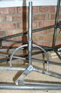
Next the semi-circular flap position tube was fabricated from 5/16" 4130 steel rod. This has to be bent to a perfect 3-1/4" radius semi-circle. This was a case of many many iterations of heat-bend-measure using a set of parallel arcs drawn on the work surface. Finally the curve was as good as I could get it and the semi-circular flap position tube inserted into the flap lever and positioned. The two short sections of 5/16" tubing that connect the semi-circular flap position tube to the fuselage centre support were then fabricated and with the lever in the most forward position the front tube tacked into place to locate the front of the arc. The lever was then moved to the upright position and the rear tube tacked into place to locate the rear of the arc and set the vertical positioning. The flap lever movement was then tested and the arc adjusted until the lever could move from fully forward to upright without any binding. This needed three iterations of cutting the rear tack - making very small changes in the arc bend and then re-tacking until finally the lever could move through its full range without binding. Then the front and rear arc supports were final welded.

Final job was to drill the holes in the arc to allow the pin in the lever inner to locate the flaps. I decided to set flap positions of 0, 7.5, 15, 30 and 40 degrees. The pushrods to the flap levers were connected and the flap levers located in place on a dummy flap tube. Using a digital level a zero degree baseline was set and the semi-circular flap position tube drilled to locate the lever in that position. Then each subsequent position was marked and drilled in turn.

The result is excellent - like much of Wittman's design it is simple, elegant and functional. The flap lever inner acts like the knob on a car handbrake and the flap positions can be selected quickly and accurately with immediate visual evidence of flap position and secure location. Would that many certified aircraft had mechanisms so simple and foolproof!
Posted by Picasa

15th July 2008 - Flap Torque tube

Finally new work. The flap torque tube was fabricated from 1" tubing with 7/8" tubing welded into each end to provide the bearing surface and locate the tube side to side. The three arms were welded to the torqe tube with the required 65 degrees between them. The centre arm is located to the left of centre so as not to interfere with the aileron control mechanism. Having learned the issue of binding on the rudder torque bars I decided to use the same approach of 16mm thick Delrin bearings for the flap torque tube. 0.071" 4130 sheet was welded to the inside of the fuselage diagonals that support the torque tube. As per the rudder, the right hand one was cut into a "U" shape to allow the torque tube to be removed once the bearing blocks are unbolted. There is no requirement for any centre support for the flap torque tube.

This approach of using Delrin blocks for the flap torque tube mounts exactly mirrors the standard practice in the Vans RV range of aircraft.
Posted by Picasa

14th July 2008 - Rework 3

The last bit of rework was to remake the bottom section of the control column. The original restricted the forward movement of the control column somewhat. The lower section below the main forward/aft pivot is designed to narrow left/right from a bend half way down to the joint with the elevator pushrod where the two sides are welded together. In the original version this narrowing section was interfering with the square tubing that runs diagonally up to provide the control column pivot as the control column was moved forward. The new version has the taper starting 1/2" lower than the original which affords greater forward movement.
Posted by Picasa

13th July 2008 - Rework 2

The second bit of rework was to improve the freedom of movement of the rudder pedals. Originally these were mounted as per the Wittman drawings using tubing welded to the fuselage longerons to support the ends of the pedal torque bars and a third support welded to one of the fuselage diagonals. The issue is that the centre bearing can only be welded to the fuselage diagonal after the pedals are in place and it is very difficult to do this without creating some degree of binding on the left pedal torque tube which is what had happened.

The solution was to cut off the three existing mounts and replace these with 0.071" 4130 sheet fabricated to support 16mm Delrin (acetal) blocks. The side plates were welded to the inside of the lower fuselage longerons. The centre one was welded on top of the lower diagonal and brake support tubes. The Delrin blocks were drilled at the requisite angle to provided the bearings for the torque tubes. As can be seen in the picture, the right hand mount was fabricated in a "U" shape to allow the rudder torque tube to be lifted out from that side and then slid out of the left hand mount. The centre Delrin support was made in two halves for easy removal. The bolts in the picture are temporary and will be replaced with machine screws countersunk into the Delrin to allow the fuselage sides to fit flat.

This approach of using Delrin blocks for the rudder torque tube mounts exactly mirrors the standard practice in the Vans RV range of aircraft.

Together the changes have much improved the freedom of movement of the rudder pedals as well as allowing them to be removed if necessary.
Posted by Picasa

12th July 2008 - Rework

After an extended pause in the building process while the real world intervened it's back to work.

First jobs are to rework the little bits and pieces that have been niggling because they are not as good as they could be.

Previously I have shown the linear bearing used to support the elevator pushrod. This was a beautiful piece of engineering but was adding too much friction to the control linkage. This was a result of two issues. First, the bearing had a rubber oil seal at both ends which was tight on the pushrod. Second, the bearing is designed for a precision 3/4" rod rather than the 4130 tubing forming the pushrod.

The challenge was to replace the bearing without remaking the pushrod. This was accomplished by drilling a clearance hole in some Delrin (acetal) rod and then sawing it in half. The two halves were then inserted into a piece of tubing of the same external diameter as the original bearing and secured using grub screws. This was then inserted in place of the bearing and has provided a very smooth support for the pushrod with very little friction


Posted by Picasa