Monday 26 April 2010

26th April 2010 - Basic assembly of the left wing

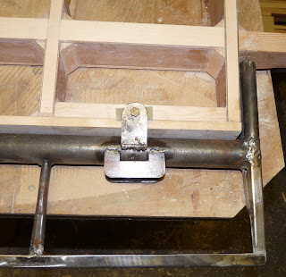
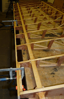
Yesterday I positioned the left wing ribs onto the main and rear spars, drilled and screwed the inner leading edge and aileron spar into position and glued the spar root doublers and bushings into place. Today I drilled the main spar attach bracket to the spar. You can see the yellow swarf in the foreground that comes from drilling through the phenolic linen bushes - strange stuff!
I'm going to be busy over the next two to three weeks so not likely to make much progress but this will give me a chance to do some planning of the next steps as I want to make sure the wings align correctly to the fuselage before closing them up.
Posted by Picasa

Saturday 24 April 2010

24th April 2010 - Left wing spars

A couple of days ago I laminated the two sections of Douglas fir to make the main spar for the left wing. Today, now the glue is thoroughly set I cut the spar ends on both the main and rear spars using the CNC router. As before, holes were drilled with the router for bushing to take the mounting bolts. The lower picture shows the spars marked out for the rib positions. I've included a couple of videos of the CNC router in action for those of you who are interested.
Posted by Picasa

Monday 19 April 2010

19th April 2010 - Locating the ailerons and flaps

I finished the sanding of the wing ready for covering today and then decided to match drill the ailerons and flaps to the wing structure before covering so that it would be easy to get the holes correctly aligned. I used two small pieces of 1/8" thick fibreglass top and bottom to represent the thickness of the wing skins (3/32") and the fabric covering and paint and two more pieces either side of the hinge to space the torque rod off the aileron spar. This 1/8" gap will allow room for the fabric covering of the control surfaces to wrap round their leading edges as well as provide clearance for the fabric covering the wing. The torque tube was clamped into position against the aileron spar and the hinges match drilled through the support blocks in the wing structure. The lower picture shows the aileron mass balance which in normal flght is in a slot flush between the wing and wing tip.
Posted by Picasa

Sunday 18 April 2010

18th April 2010 - Sanding and more sanding

This week time in the workshop has been spent sanding. The main spar caps, rear spar caps, inner leading edge, and aileron spar all needed sanding to final size to blend in with the ribs top and bottom. I made up a sanding block long enough to sand across four ribs at a time by cutting open a sanding belt and gluing it to a length of flat timber. Using this it was possible to blend in the joints without risking sanding dips into the timber between the ribs but it is slow progress and hard work. As at today the wing is complete except for the upper rear spar capsticks and upper aileron spar so I'm about 80% complete. The bottom picture shows the way the upper surface of the root rib and inner leading edge have been tapered to allow the skin to glue in place.
Posted by Picasa

Tuesday 13 April 2010

13th April 2010 - Root rib inner leading edge, aileron and flap mount blocks

First job today was to pin and glue a section of timber between the leading edge of the root rib and the first main rib. This will act as the inner section of the leading edge for the first bay of the wing. Once shaped, it will be covered in the ply skin and then the outer section of the leading edge will butt join to it and overlap the skins. Next blocks of timber were cut to fit between ribs 1&2, 5&6, 9&10 and 12&13. These were glued into place and will be drilled through the wing skin to take the bolts that secure the flap and aileron hinges to the wing.
Posted by Picasa

Monday 12 April 2010

12th April 2010 - Strut attach bracket

The outer bush for the strut attach bracket was first drilled through using a 3/8" hole in my jig block as a guide to make sure the hole was perpendicular. Then the other bush was match drilled about 1/4" deep to establish the hole location. The bracket was removed and this was then also drilled through using the jig block. This worked well to keep the spacing and alignment of the holes accurate and the bottom bracket fitted nicely over the bolts. Then the upper 1/4" thick 12-ply plate was glued to the spar. Once the glue was set the brackets could be bolted into position. The bushing material is very solid and it was possible to torque the bolts to the specified torque for a 3/8" bolt of 160 in/lb without compressing the wood of the spar.
Posted by Picasa

Sunday 11 April 2010

11th April 2010 - Strut attach bolt bushes and corner blocks

First job today was to mark the locations of the two strut attach bolts between ribs 7 and 8. Two 3/4" holes were then drilled to take the bushing material which itself will be drilled for the 3/8" bolts that fasten the strut attach brackets to the main spar. The bushing was then glued into place together with the rear 1/4" thick 12 ply plate. The 3/8" holes will then be drilled through the centre of the bushes and the rear ply plate. Then the front ply plate can be installed and finally the bolt holes drilled through it as well.
Then it was a case of gluing and pinning the corner blocks that strengthen the joints between the spars and the ribs, easy enough but took most of a day to complete - this must be the equivalent of dimpling when building in aluminium. This completes most of the wing structure, remaining jobs are to install the leading edge between the root rib and rib #2 and four blocks along the aileron spar to take the aileron and flap attach bolts. Then it's time to sand everything ready for the lower wing skin. The wing tip will not be constructed until after the lower skin is glued into place. I still haven't decided whether to do an all wooden wingtip or the original Wittman design which uses metal tubing to create the aerofoil shape.
Posted by Picasa

Saturday 10 April 2010

10th April 2010 - Inner leading edge and aileron spar

Two of the wood strips that I cut last week were marked up, drilled, and countersunk to attach them to the front and rear of the ribs. Then each rib was match drilled front and back with a guide hole to take #6 wood screws. The inner leading edge strip was then screwed and glued to the front of the ribs, then the aileron spar was screwed and glued to the rear of the ribs. Next triangular sections of wood with one right angle were cut to length to make corner blocks which will secure the ribs to the main spars and to the leading edge and aileron spars. Using a jig in the drill press to locate the triangular sections nose down, the blocks were then each drilled in two places to take panel pins which will secure them to the spars while the glue dries. I made enough blocks for both wings, the ones for the left wing are in the plastic bag in the foreground of the picture - lots of cutting and drilling.
Posted by Picasa

Friday 9 April 2010

9th April 2009 - The right wing root rib

Just 30 minutes to give to the project today so I finished preparing the spar roots for the root rib and glued in place the rib and the upper spar caps between it and the first main rib. Now this is in place I can install the aileron spar and inner leading edge.
Posted by Picasa

Sunday 4 April 2010

4th April 2010 - Right wing lower spar caps and spar attach brackets

Today I drilled the spar roots for the spar attach brackets. First I drilled a piece of 3/4" thick aluminium with 3/16" and 1/4" holes using the drill press. This would then act as a guide to ensure the holes were drilled accurately through the spars. The the attach brackets were positioned over the line of the bushes glued into the spar and the holes drilled one at a time with a bolt inserted in each hole before drilling the next. The drill guide worked well and all of the holes came out accurately in line with the holes in the far side of the attach brackets.
Then the spar roots were notched to fit snugly into the root rib with the rear top section of the root rib aligned with the tops of the main ribs as per the plans.
The lower main and rear spar caps were glued into place between the ribs.
The strut attach is into the main spar between ribs 7 and 8. The LAA require that the holes for this are also bushed and that the spar is reinforced with 1/4" ply either side. Their specification for 12-ply material. As this doesn't seem to exist I cut 4 pieces of 1/16" birch three ply and epoxied these together alternating the grain direction, clamping them between layers of plastic to wait for the epoxy to set.
Posted by Picasa

3rd March 2010 - Preparing the wing leading and trailing edges

The first job today was to shape the sections of wood that will form the leading and trailing edges of the wing. The 3/8" thick stock material for the aileron spar and the inner section of the leading edge nose block had been supplied as 6" wide sheets so a combination of the bandsaw and the table saw were used to convert this to the sections needed. The aileron spar has an angle of 87 degrees on the lower edge and 80 degrees on the top edge. The inner nose block has an angle of 60 degrees on top and 79 degrees on the bottom. Angles up to 20 degrees can be cut on the bandsaw but above that the table saw is needed. After setting up the saw tables with fences and feather boards to hold the material test cuts were made on scrap material to adjust the sizes precisely. The final cuts were then made to exact size to butt precisely against the ribs and to require no further adjustment before gluing the skins in place. The aileron spar and inner nose block fit inside the wing skin. The outer nose blocks butt onto the front of the inner blocks and the edges of the skins. These were cut slightly over size and will be shaped by hand to form the leading edge shape. These were cut using the table saw from 1" x 2" stock. First this was resawn into two 7/16" x 2" sections and then the angles cut into the edges.
Then the 1/16" ply reinforcing plates were glued to the sides of the spar roots. The second and third pictures shos the wing mounts in place. The ply and spar bushes will be drilled to secure these in place. It is important that the mounts butt tightly against the ends of the spars as many flight loads are compressive and this tight fit provides additional strength to the joints.
Posted by Picasa

Saturday 3 April 2010

2nd April 2010 - Right wing upper spar caps

Now that I had a completed set of spars for the right wing I could start the main construction effort. First job was to thread the ribs onto the spars - easier said than done! The plans say to make the ribs a snug fit and they are. The only way I found to get them onto the spars was to tap the ribs an inch at a time, first along the main spar, and then along the rear spar. As the centre rib is 5ft from either end this took some time. However, after a couple of hours of gentle persuasion the ribs were in place and miraculously a wing appeared. Next lengths of 1/4" thick 1-1/4" and 1" wide spruce were cut to fit along the tops of the spars between the ribs. These were then epoxied into place to form the upper spar caps.
Finally today lengths of 3/4" linen phenolic rod were cut to fit in the holes in the spar roots and epoxied into place. This material is specifically designed to provide high-strength close-tolerance bolt holes in wooden spars and is available from ACS.
Posted by Picasa

Friday 2 April 2010

1st April 2010 - Right wing spars

As the glue laminating the front spar was now properly set, I could create the root shapes for the spars and the tapers at the wingtips. Having built a computer controlled router I decided to use this to do the work. So I programmed the outlines of the four ends into Cambam which is CAM software with some limited 2.5D CAD capability. Then I positioned the first spar ready for the cut. Mach 3 software is used to control the machine. Good practice is to try the machine program with the cutter set above the workpiece so that you can observe the pattern without cutting the wood. Once I was satisfied with the program, the cutter height was set down and the program started for real. In fact on the first end of each spar there would be an opportunity to redo the cut in the event of problems as the stock material was long enough but this wouldn't be the case on the second end. In fact, the cuts all went well and the programs can be re-used for the second wing.
At the root ends I used the program to cut 3/4" holes where the bolts will go. These will be filled with some special bushing material epoxied in which will be final drilled to the finished size. This ensures that the bolts will not move in the wood and increases the strength of the joint by increasing the diameter of the hole in the wood.
I was particularly pleased with the wing tip taper cut on the main spar shown in the second picture. Trying to do this by hand would have been difficult and the router did a perfect job (last picture).
The cutter used is a 1/4" carbide cutter specifically designed for wood. I set the program to cut 1/8" deep at each pass, first cutting 1/16" outside the cut line and then at each depth cutting exactly up to the line. The linear rate of cut was set to 16" per minute. So to cut the full 1-1/4" depth of the main spar takes 20 passes - quite slow but a perfect result.
The holes were drilled with the same 1/4" cutter. The computer control moves the router bit in precise circles and the result is far better than could be achieved with any sort of wood drill and is of course perfectly vertical. Also the size can be adjusted to get just the right sort of fit to allow the bushing to be inserted and leave enough room for the glue layer.


Posted by Picasa