I have to confess that I'm finding making ribs pretty boring, so a couple of days ago I painted the panel in it's final matt black and today installed the various instruments in it. Assuming my build sequence for the completed aircraft is correct, I should be able to install the panel complete with instruments and wiring without them having to be removed again so the photo gives a good impression of how the completed panel will look. From top to bottom, left to right the layout is as follows:
Starter engaged warning light
Mag switches (left and right)
Master/Alternator switch
Starter Push Button (NB, the mag switches have to be left impulse mag-on, right-off for this to operate)
Vacuum gauge
Tachometer
Hole for Trig TT21 Mode S transponder (mode S mandatory in Europe)
Pilot headphone sockets
Airspeed Indicator
Trio Autopilot
Artificial Horizon
Directional Gyro
Primer
Altimeter
Vertical Speed Indicator
Warning light Cluster (Low volts, Low Oil pressure, Carb temperature, Autopilot Engaged)
Information Display Unit (GPS Heading, GPS Groundspeed, Air Temperature, Carb Temperature, Bus Voltage, Battery Amps)
Garmin Apollo SL30 Nav Comm
Bendix King KMD150 GPS
Holes for Carb Heat, Throttle, Mixture
Oil Temperature and Pressure gauge
Intercom
Switches for: Strobes, Nav Lights, Auxilliary Fuel Pump, Spare for future requirement
Hole for CHT/EGT gauge
Fuel gauge
Pullable Breakers for alternator field and starter relay
Hole for Cabin Heat Control
Speaker On/Off switch
Chronometer: Time, Stopwatch, Flight-time
Emergency electrical power switch
Passenger headphone sockets
Spare 2-1/4" hole to be covered with panel blank pending any future requirement
12V Power Outlet
The intention of the panel design is to have good functionality but stay in keeping with the ethos of the aircraft and it's design date, hence the predominantly analogue instrumentation. The instrumentation also has to fit in with the physical requirements of the aircraft - particularly the depth limitations created by the fuel tank. I'm pleased with the way it has turned out but obviously the proof will be in flight.
Remember throughout the blog you can click on the pictures to see them enlarged.

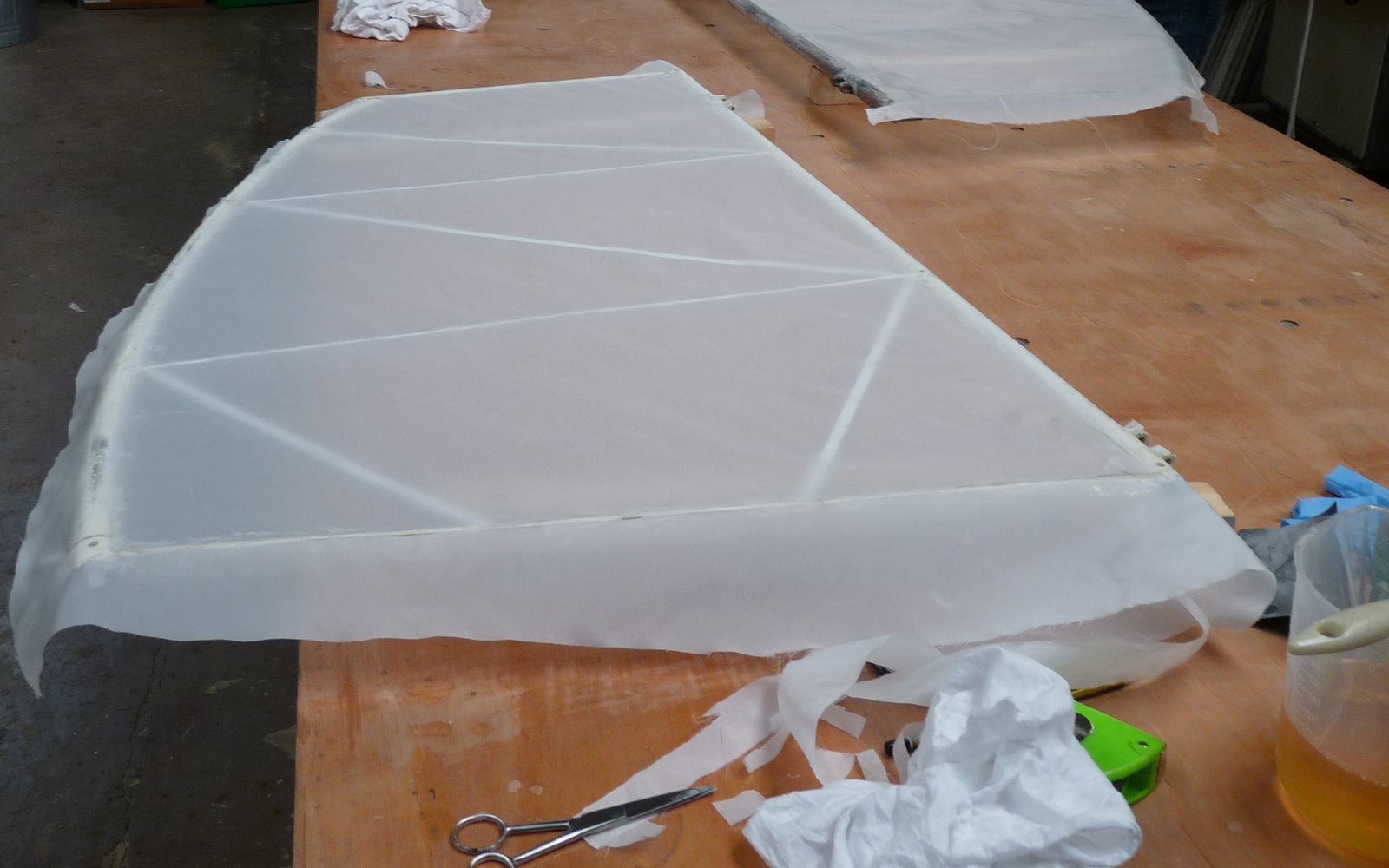
 Since I'm now "fully" trained I though I'd better make a start on covering before I forget everything. The smallest piece to be covered is the rudder so that seemed like the place to start. I'm using the Stewart Systems covering process (http://www.stewartsystems.aero/) which has the advantage that the glue and all of the paints are water bourne which results in much reduced smell and hazard. The process is STC'd for use on most if not all certified fabric covered aircraft. Full details of the covering process including the manual are on the web site and there are also links to very helpful videos showing each stage. So it was a case of following through the steps I'd learned but using the Stewart glue. With such a small piece the result seems to be all rib covering tapes and finishing tapes but I'm reasonably pleased with the result and hopefully my inspector will be happy with the standard.


