
Having spent ages working out the order to install things in the fuselage I've made a start. I have decided to cover the fuselage on its wheels which means I can do most of the interior fit out and wiring before covering. The biggest puzzle has been the order in which to install the panel, fuel tank and combing in order to make both the install and future maintenance easy and minimise the amount of repeatedly installing and
de-installing things during the build. So I'm now committed. The first job was to cover the interior of the firewall with some self adhesive felt material I found. This makes a nice finish and should damp vibration a bit. I tested the material

for the impact of both heat and flame and it passed with flying colours - refusing to burn at all and just shrivelling a bit when a 400 degree C heat gun was played on it. The firewall was first screwed to the tabs on the frame and then the major firewall mounted components added. Then the panel with the power distribution unit was
temporarily installed. The major power cables were then cut to length and terminated: switched power,
unswitched power, earth, starter energise, main
contractor energise, alternator field, starter warning, ammeter sense. The last picture shows the power distribution unit. This

implements the Z11 schema for a generic light aircraft electrical system as documented in the
Aeroelectric connection manual by Bob
Nuckolls. The small
fuseblock provides
unswitched power for the power socket, clock and via a switch emergency power for the endurance bus. The large fuse block is the endurance bus and is powered either by the starter
contactor via a diode or the emergency power switch. All
essential services will be wired to this (radio, transponder, intercom, etc.) The bus bar connecting the fuses and switches is the main power bus. The two
pullable fuses on this are for the alternator field and starter. The four switches are for the fuel pump, the
nav lights, the strobes, and the autopilot (a separate switch for this is a mandatory requirement in the UK). The terminal strip along the bottom provides a ready supply of earth connections.
 Having spent ages working out the order to install things in the fuselage I've made a start. I have decided to cover the fuselage on its wheels which means I can do most of the interior fit out and wiring before covering. The biggest puzzle has been the order in which to install the panel, fuel tank and combing in order to make both the install and future maintenance easy and minimise the amount of repeatedly installing and de-installing things during the build. So I'm now committed. The first job was to cover the interior of the firewall with some self adhesive felt material I found. This makes a nice finish and should damp vibration a bit. I tested the material
 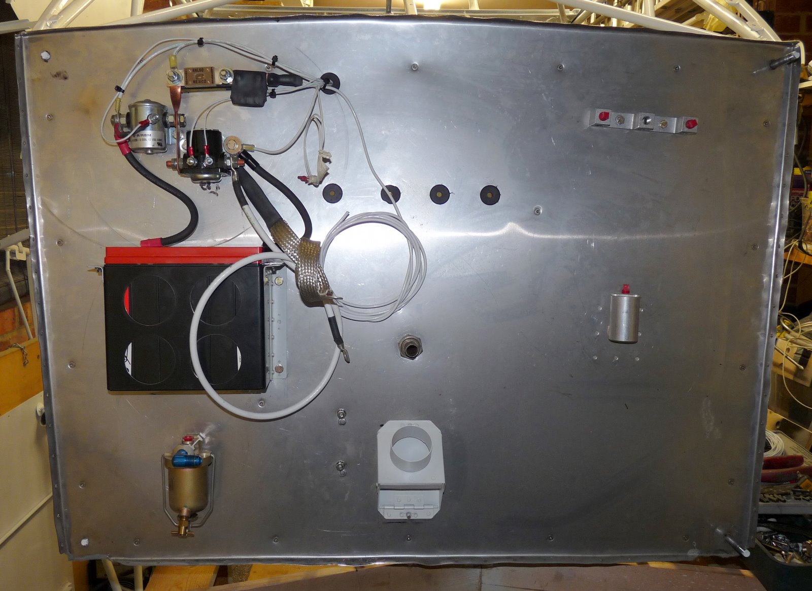 for the impact of both heat and flame and it passed with flying colours - refusing to burn at all and just shrivelling a bit when a 400 degree C heat gun was played on it. The firewall was first screwed to the tabs on the frame and then the major firewall mounted components added. Then the panel with the power distribution unit was temporarily installed. The major power cables were then cut to length and terminated: switched power, unswitched power, earth, starter energise, main contractor energise, alternator field, starter warning, ammeter sense. The last picture shows the power distribution unit. This
  implements the Z11 schema for a generic light aircraft electrical system as documented in the Aeroelectric connection manual by Bob Nuckolls. The small fuseblock provides unswitched power for the power socket, clock and via a switch emergency power for the endurance bus. The large fuse block is the endurance bus and is powered either by the starter contactor via a diode or the emergency power switch. All essential services will be wired to this (radio, transponder, intercom, etc.) The bus bar connecting the fuses and switches is the main power bus. The two pullable fuses on this are for the alternator field and starter. The four switches are for the fuel pump, the nav lights, the strobes, and the autopilot (a separate switch for this is a mandatory requirement in the UK). The terminal strip along the bottom provides a ready supply of earth connections.