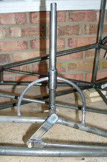
Now for the interesting bit of the flap mechanism. First the flap pivot bearing tube was welded to the fuselage centre support. The flap actuating arm was then welded to the pivot itself. The outer part of the flap lever was then fabricated with a section of 7/8" tube in the centre drilled 3/8" to pass round the semi-circular flap position tube. The plans show the 7/8" tube welded to the 5/8" flap lever. This doesn't work as the fit is far too loose so a section of 3/4" tube was also inserted. I assume the 7/8" tube is called for to allow the 3/8" hole to be drilled without compromising the strength of the lever. The completed outer lever was then welded to a section of the same 3/4" tube used for the pivot bearing. This was then installed on the pivot allowing space for the pivot bearing and with the requisite 38 degrees between the lever and the actuating arm. This was then match drilled through the pivot for an AN3 bolt.
The flap lever inner was then fabricated with a vertical slot through which the semi-circular flap position tube passes. At the bottom of the slot a disc was braised in place with a vertical 1/8" pin in the centre. This locates in holes in the semi-circular flap position tube to lock the flaps into their various positions. The top of the inner was closed with another disc of metal braised in place to provide the "thumb" position. The inner then inserts into the outer part of the lever with a spring underneath it to load the inner from underneath and push the pin towards the semi-circular flap position tube. The whole mechanism was then located in place through the bearing and the AN3 bolt inserted.
Next the semi-circular flap position tube was fabricated from 5/16" 4130 steel rod. This has to be bent to a perfect 3-1/4" radius semi-circle. This was a case of many many iterations of heat-bend-measure using a set of parallel arcs drawn on the work surface. Finally the curve was as good as I could get it and the semi-circular flap position tube inserted into the flap lever and positioned. The two short sections of 5/16" tubing that connect the semi-circular flap position tube to the fuselage centre support were then fabricated and with the lever in the most forward position the front tube tacked into place to locate the front of the arc. The lever was then moved to the upright position and the rear tube tacked into place to locate the rear of the arc and set the vertical positioning. The flap lever movement was then tested and the arc adjusted until the lever could move from fully forward to upright without any binding. This needed three iterations of cutting the rear tack - making very small changes in the arc bend and then re-tacking until finally the lever could move through its full range without binding. Then the front and rear arc supports were final welded.
Final job was to drill the holes in the arc to allow the pin in the lever inner to locate the flaps. I decided to set flap positions of 0, 7.5, 15, 30 and 40 degrees. The pushrods to the flap levers were connected and the flap levers located in place on a dummy flap tube. Using a digital level a zero degree baseline was set and the semi-circular flap position tube drilled to locate the lever in that position. Then each subsequent position was marked and drilled in turn.
The result is excellent - like much of Wittman's design it is simple, elegant and functional. The flap lever inner acts like the knob on a car handbrake and the flap positions can be selected quickly and accurately with immediate visual evidence of flap position and secure location. Would that many certified aircraft had mechanisms so simple and foolproof!

 Finished the rudder ready for priming. Started by jigging the bottom tube to the rudder front spar on the bench and tack welding it then final welding it. The rear of this tube is progressively flattened to fit the V" section stainless steel trailing edge. Then mounted the rudder on the fin spar locked in a centralised position. Fastened in place the trailing edge from the bottom tube up past the top of the rudder to the top tube of the fin. This ensured that the slope of the trailing edge would align correctly into the top section of the fin. The trailing edge was then brazed in place at both ends. I then fabricated the top rib of the rudder from two pieces of 3/8" steel channel. The ends of these were tapered to form the aerofoil shape of the rudder and were then tack welded together with the forward end at the requisite 3/4" width to mate with the rudder front spar. The forward end was then ground into the semi circular shape of the spar with the length correct to snuggly fit between the spar and the trailing edge. This was then brazed into place. The second and third ribs were then fashioned in the same way and brazed into place. The trailing edge was then cut at the top of the rudder with the remaining section left in position to form the trailing edge of the top section of the fin. I had originally intended to leave this in one piece until I installed the ribs in the fin but realised that brazing the fin rib would also melt the top rudder rib joint if it was still connected.


