- Apply second brush coat of EkoFill to fuselage sides
- Mask fuselage internals and spray 2 crosscoats of filler on to fuselage sides
- Apply EkoFill to control surfaces: rudder, two off ailerons, two off flaps, two off elevators, two off horizontal stabilisers
- Make drainholes in control surfaces
- Apply EkoPoly to control surfaces
- Prime and top coat all cowl attach brackets and spacers
- Final fit front fuselage side panels and rivet into place on firewall with cowl attach brackets
- Reprime front fuselage sides with EkoPrime to ensure topcoat colour match
- Reprime front fuselage lower panel with EkoPrime to ensure topcoat colour match
- Cut access hole in combing to allow fuel level sender to be calibrated, make and fit removable cover
- Respay combing and refit
- Fabricate internal and external cover plates over tank filler hole in windscreen, prime and topcoat
- Install tank filler in windscreen and refit windscreen
- Rivet Front windscreen edge strip to firewall and cowl attach brackets
- Rivet lower cowl attach brackets to firewall
- Prime undercarriage legs
- Topcoat complete fuselage and undercarriage with white EkoPoly
- Final weld right door latch
- Fabricate left and right door latch covers
- Fabric cover left and right door internal structure
- Apply EkoFill to door internal skins
- Topcoat doors with white EkoPoly
- Fabricate and install remaining transparencies: Two off door, two off forward fuselage sides, two off rear fuselage sides
- Seal inside of airbox with pigmented resin
- Paint topcoat airbox metalwork
- Rivet together airbox
- Apply second coat of pigmented resin to seal inside of top cowl
- Final fit cowl
- Fill pinholes in cowl and prime
- Topcoat cowl with white EkoPoly
- Install cowl and mask for applying red fineline along fuselage and cowl
- Topcoat spinner backplate with red EkoPoly
- Spray fineline with red EkoPoly
- Apply glass cloth reinforcement to top of leg spats
- Prime leg spats with EkoPrime
- Topcoat leg spats with white EkoPoly
- Drill undercarriage ends to take cotter pins to secure wheel nuts
- Install brakes
- Fabricate brake pipes, fill, bleed, and pressure test brake lines
- Test install wheel spats, fabricate inside support bracket to fit
- Sand and prime wheel spats
- Topcoat wheel Spats with white EkoPoly
- Fabricate engine baffles
- Fabricate engine exhaust system
- Fabricate leg to fuselage intersection fairings
- Fabricate leg to wheel spat intersection fairings
Saturday, 31 March 2012
31st March 2012 - To Do list
Today I spent stripping out various internals ready for spraying. I also set about working out a to do list to complete the fuselage (this will still leave the wings to be skinned) as follows:

Friday, 30 March 2012
30th March 2012 - Finally some painting progress!


Sunday, 6 November 2011
6th November 2011 - Carburettor heat control

 One more little job completed today. A semi-circular shaped hole was cut out in the top of the airbox and one half of a piece of hinge match drilled to its straight forward edge. Then an aluminium flap was created to completely fill the normal entrance to the airbox when at right angles to the airbox top. This took lots of iterations of filing and testing to exactly fit the shape of the fibre-glass bottom of the airbox. Once this was a good fit it was match drilled to the other side of the hinge. The holes were then deburred and dimpled to take countersunk rivets. These were set so that the flush surface is inside the airbox to provide minimal disturbance to the airflow when in the normal open position. Then an actuator arm was rivetted to the top of the flap and drilled for a cable connection. The top of the airbox was then bolted to the carburettor and the actuator cable measured and cut. The system is designed so that the cable pull holds the flap open against the airflow when carb heat is required. In the normal closed position the control is fully forward and the cable is assisted by the airflow to keep the flap tight to the top of the airbox and allow the cold air into the carburettor. The hot air intake is mounted over the semi-circular cut out and is spaced off it to allow the heated air to spill into the cowl when carb heat is not required. When heat is required the suction of the carburettor will ensure hot air enter the airbox. The six tabs on the underside of the airbox top-plate hold the K&N filter in position.
Friday, 4 November 2011
4th November 2011 - Lower cowl nearly complete
 It has been slow progress over the last few days. The weather has been poor so I haven't been able to get the fuselage outside and I'm spending time waiting for resin to cure. Finally though the airscoop is fully bonded to the cowl and the air intake created and lined up with the airbox. The process for creating the air intake is to cut the hole in the airscoop to match the intake to the airbox then shape and insert a foam plug that projects into the airscoop. Glass cloth is then laid up around this plug to create a tube on the inside of the airscoop that matches the airbox. The airbox will then have a rubber seal riveted around the intake that fits over the tube in the airscoop that has been fabricated. This ensures that outside air is rammed into the airbox by the propeller and speed of the aircraft increasing the effective air pressure at the carburettor and therefore the engine power. I just need to wrap one final layer of glass round
  the lips of the air intake to protect them and final fill and sand then the lower cowl will be finally ready for priming.

Tuesday, 1 November 2011
1st November 2011 - Brakes and cowl
 The first job today was to complete the installation of the brakes. The top end of the master cylinder pistons were connected to the brake bars on the rudder pedals. Then the fluid intakes were connected to the "T" junction on the fluid reservoir. Finally, the fluid outlets were connected to the AN fittings screwed through the floor. These will then connect to the brake lines running down inside the leg fairings. Next the front cheek panels were covered on the inside with the same self-adhesive felt fabric as the baggage compartment walls. These were then clecoed into place ready for riveting to the firewall.
The posting on the 26th October shows how I had had to cut the airscoop in half horizontally in order to increase its depth. Yesterday, I had put a first layer of glass on the inside of the gap to join the two halves and put a slurry of resin and microballoons on the outside to level up the surface. I had also put a first layer of glass over the joint between the top section of the airscoop and the cowl proper. Today, the joints were sanded to create a key and two extra layers of glass were glued into place over both the joints. The three layers should be enough for a final result but I'll check it tomorrow to see if I think it needs one extra layer. Then the cowl was inverted and a slurry of resin and microballoons used to filet the intersection between the airbox and cowl. This can be easily sanded once set to get a clean smooth joint. Any resin left over from each layup is mixed with some white pigment and painted onto the inside of the cowl. Once completed properly this will seal the inside of the cowl and allow any drips from the engine to be easily seen. Finally three layers of glass
 were applied to the joint in the airbox. Once this is set I will filet the inside of the joint to make sure that the air can flow smoothly into the filter.


31st October 2011 - Spraying the underside
 It was good weather today so the aircraft was tipped on its nose once more to spray the underside with the white EkoPoly topcoat. The paint has gone on pretty well with no runs or other serious blemishes. However the edges of the finishing tapes are very obvious. Before I do any more painting I'm going to have to make sure these are really stuck down and lie as flat as possible. However, this sort of learning experience is one of the advantages of doing the bottom first. This is not a view that is going to be routinely seen!
Monday, 31 October 2011
30th October 2011 - Dzus fasteners
 I decided to use Dzus fastners to fasten the cowl to the mount strips. These are not the completely flush types (which are silly money!) but appear as a flat screw head on the outside. They take a quarter turn with a screwdriver to fasten and unfasten. The cowl mounting strips were removed and the cowl mounting pilot holes drilled out to 7/16" to take the raised surround of the Dzus "nut". Then 1/8" holes were drilled for the mounting rivets. The mounting strips and the fasteners were dimpled to accept countersunk rivets. AN426AD4-4 rivets were inserted and set using the pneumatic squeezer. Then the holes in the cowl were drilled out to take the Dzus "screws". The mounting strips were then clecoed back into place and the cowl replaced and checked for fit. Then the front inner floor was also installed and screwed into place and the rudder system installed.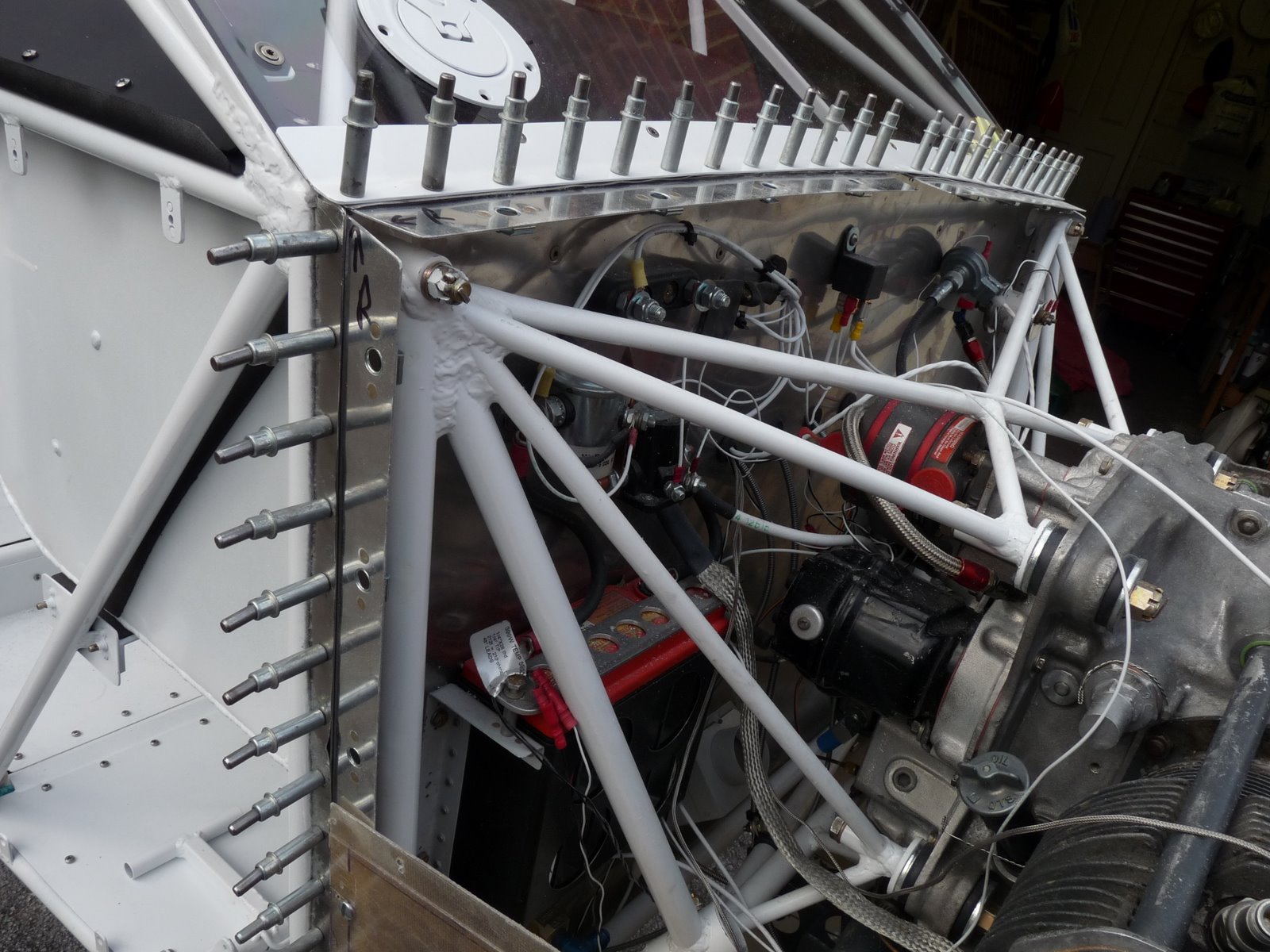

Subscribe to:
Posts (Atom)