Monday, 31 October 2011

30th October 2011 - Dzus fasteners

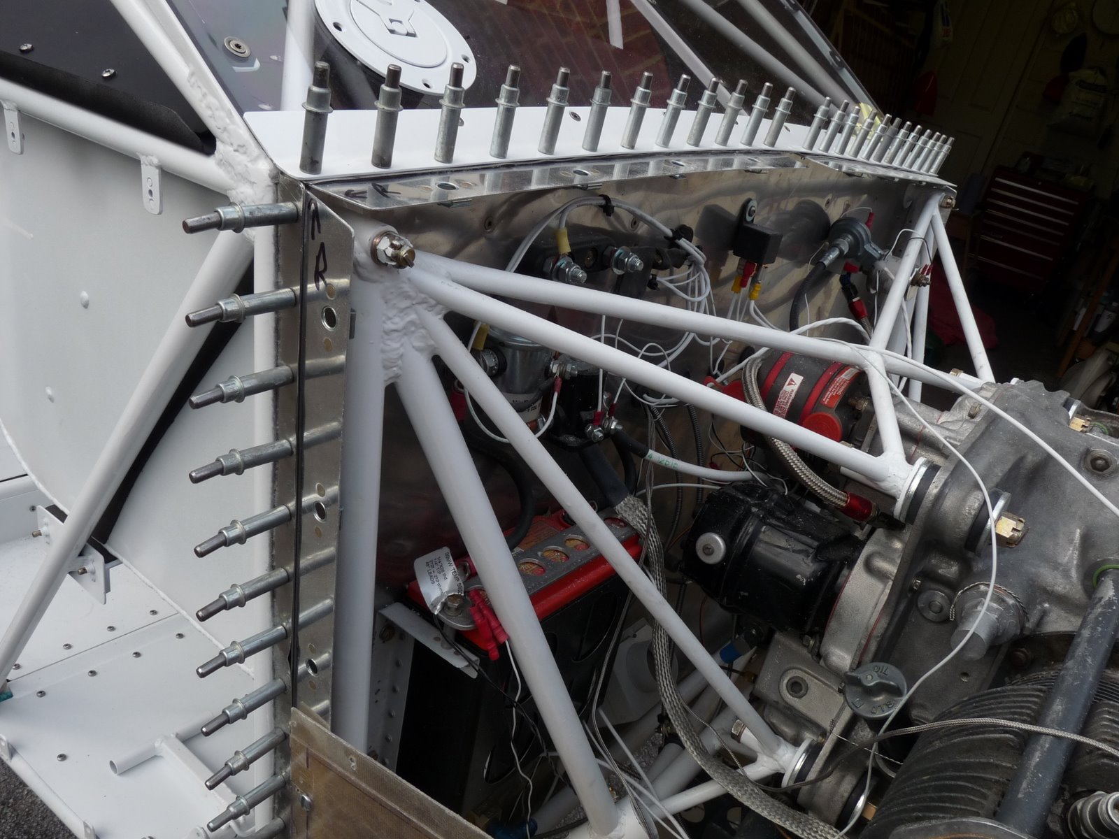
I decided to use Dzus fastners to fasten the cowl to the mount strips. These are not the completely flush types (which are silly money!) but appear as a flat screw head on the outside. They take a quarter turn with a screwdriver to fasten and unfasten. The cowl mounting strips were removed and the cowl mounting pilot holes drilled out to 7/16" to take the raised surround of the Dzus "nut". Then 1/8" holes were drilled for the mounting rivets. The mounting strips and the fasteners were dimpled to accept countersunk rivets. AN426AD4-4 rivets were inserted and set using the pneumatic squeezer. Then the holes in the cowl were drilled out to take the Dzus "screws". The mounting strips were then clecoed back into place and the cowl replaced and checked for fit. Then the front inner floor was also installed and screwed into place and the rudder system installed.


Posted by Picasa

Friday, 28 October 2011

28th October 2011 - Starting painting

I want to rivet the forward fuselage cheeks and forward outer floor to the firewall but...
I can't do that until I install the rudder pedals and brakes but...
I can't do that until I install the forward inside floor but...
I can't do that until I install the forward outer floor but...
I can't do that until I have painted the underside of the fuselage so...
Today I set to to do that. I brief trial proved that painting the underside with the EkoFill primer/UV blocker was not going to be possible lying on the floor. However, without the tail feathers the airframe is currently pretty much neutrally balanced when in flying attitude and the centre of balance moves forward as the tail lifts. So the wheels were chocked and a cable attached to the horizontal stabiliser carry through and very carefully the aircraft was allowed to tip forward until the engine rested on some foam padding. This allowed enough access to the underside to work and get access with the spray gun.
The process is first to clean the fabric with some special cleaner that Stewart supply and then to wash off the detergent leaving the fabric damp. Then the first coat of EkoFill is brushed on with a foam brush. Once this is dry a second coat was brushed on using the brush at right angles to the first coat. Painting the tail while standing on a step ladder was slightly bizarre and the passing local traffic seemed distracted! While this coat was drying I decided to make a first attempt at using the Stewart EkoPoly top coat. I had previously prepared the spinner so this was an ideal test subject. The paint was mixed with the catalyst and then thinned with distilled water and then 4 coats were sprayed on alternating in direction about 10 minutes apart. The first coat came out as tiny globules of paint rather than a mist. This was diagnosed as having too little gas pressure so once this was corrected the painting was much more even. There is a little bit of an orange peel effect but this should polish out and was probably caused by the first coat. After 3 hours the fuselage seemed dry and some 320 grade open coat sandpaper was used dry to remove any blemishes. Then the paint gun was prepared for 4 coats of the primer (2 coats in each direction). These were applied as per instructions about 10 minutes apart and resulted in an even light-proof covering of the fabric. This is critical as the fabric is degraded by ultra-violet light and left outside unprotected will loose 85% of its strength in a year. The fuselage was then gently returned to a more normal attitude and returned to the workshop where the paint can harden overnight.
Posted by Picasa

Thursday, 27 October 2011

27th October 2011 - Main gear leg fairings

It is an unpleasant day, rainy and cold, so I needed a task that could be accomplished inside with the aircraft in the workshop. I had acquired the blanks for a pair of the old style aluminium Vans gear leg fairings so fitting these seemed like and ideal job. First the fairing were cut to size to fit between the fuselage and the wheel. The fairings are joined at the back by inserting the pin in a length of aluminium hinge. The key to a neat job is to have the hinge positioned so that when the fairing is flexed around the gear leg it pulls the trailing edge of the fairing together precisely. Pieces of scrap steel tube were used to simulate the ends of the gear legs and with the rear edge of the fairings taped together the correct position of the sides of the hinges marked. The hinge pin was then removed. The ends of the hinge were match drilled to the fairing and then a rivet fan spacing tool was used to get an even line of rivets. In theory you are not supposed to drill through the fan to avoid opening up the holes, just use them to mark, but I'm sure I'm not alone in ignoring this advice. Once all the holes were drilled they were dimpled to accept countersunk rivets. With the thin aluminium and the thin hinges this could be done through the two together which ensures a very good fit. Then the rivets were set using the pneumatic squeezer - it is great to have these tools left over from the RV build. The result is a exactly spaced set of perfect rivets - this is one of the most satisfying jobs when it comes out well. The fairings were then wrapped round the gear leg and the natural position of the top of the legs in the fairing established. This was marked and then slots cut in the top of the fairings stop drilled at their bottom ends. Stainless steel jubilee clips were then used through the slots to fasten the fairings to the leg. Before flight they need very accurately aligning fore and aft with weight off the wheels as if misaligned they act as mini rudders and can put the aircraft out of balance.


Wednesday, 26 October 2011

26th October 2011 - Cowl, Airscoop, and Airbox

The first job today was to roughly cut out the lower cowl for the airscoop. The lower cowl was then match drilled to the cowl support strips in the same way as the upper cowl. This immediately revealed a problem. The airbox stuck out way below the cowl at the front and was also about an inch further below the cowl at the back than the depth of the airscoop. I assume the RV9 has a greater vertical cross section than the Tailwind hence the difference. Whilst I was pondering what to do about this I removed the cowl to finalise the fit between the upper and lower cowls.
It was clear that the only solution was some fairly major fibreglass surgery. The first job was to get the top of the air intake on the airbox to align just below the bottom of the lower cowl. Notches were cut in the flange of the top plate of the airbox just in front of the filter and the plate bent up about 15 degrees. Reinforcing angles were cut out and clecoed on the inside of the flanges to hold the angle. Then the fibreglass box was cut in half and the front section angled to match the bend. Slots were cut in the front edge of the rear section and heat used to bend the tabs in to butt join accurately with the front section.
Next the airscoop was cut in half horizontally. The lower cowl was cut out to match the top section of the airscoop which was then taped in place. The cowl was then refitted to the aircraft. This allowed the bottom section of the airscoop to be positioned which showed that it needed to be about 1/2" lower at the front and 1" at the back. The sides of the bottom section were notched to allow the front to curve up slightly. Some scrap aluminium was clecoed to the top section of the airscoop and the bottom section positioned to allow a small amount of clearance from the airbox. This was then drilled and clecoed to the aluminium.


I've ordered some vinylester resin which is what was used to construct the cowl so once this arrives I can glass over the various joints, spaces and notches. The resin can also be mixed with microballoons to make a lightweight filler to smooth over the various joints. The final job will be to make the flexible joint between the front of the airbox and the airscoop. This was pretty tricky on the RV but at least I've done it once before.

Tuesday, 25 October 2011

25trh October 2011 - Cowl and air filter

I received a delivery from Vans today with some of the bits I need to make progress firewall forward but first job today was to carefully cut out the fabric round the hinges in the elevators, flaps, and ailerons with a soldering iron to free the hinges. Once this was done, strips of 0.040" aluminium were cut and match drilled to the firewall to provide the mounting for the cowl. Spacers were also cut and match drilled to fit between the cowl mounting strips and the inside lip of the firewall. The idea is that the thickness of the aluminium skin plus the spacer plus the firewall should be equal to the thickness of the cowl so that when it is fastened to the mounting strip it lies flush with the fuselage side. Then the upper cowl was positioned and match drilled to the mounting strip at 4" spacing. This will be fastened in place using Dzus fasteners to make it easy to remove.
The lower cowl has to be cut out for the airscoop that feeds air into the filtered airbox so the basic construction of the airbox was started to allow the requisite measurements to be established. I need to construct the carburettor heat control and then I can rivet it together. The airbox kit is from Vans and is identical to the one I'm using on the RV9A.
Posted by Picasa

24th October 2011 - Pitot mount and engine controls

I fancied a change of task today so decided to fabricate a mount for the pitot tube. I had a pitot left over from a Cessna I had owned that the CAA decided was not the correct part number for that plane so had to be replaced. The standard Wittman pitot is a tube through the leading edge and whilst this is light and simple it has a couple of drawbacks. At high angles of attack it is reported to significantly under read and it is vunerable sticking out from the front of the wing (and also possibly dangerous to eyes whilst the aircraft is on the ground). The conventional pitot should be more accurate as the underside of the wing will channel air past it even at high angles of attack and is certainly less vunerable. The starting point for the mount was purchasing a length of streamlined steel tubing 2.023" x 0.857" x 0.049" which is a standardly available size and fits perfectly around the stem of the pitot - I presume this is deliberate. Then a plate of 0.063" steel sheet was cut to fit round the streamline tubing and a second plate drilled to attach to the rear of the wing main spar. These were then jigged against the spar using some scrap timber and the joint tack welded to get exactly the correct angle (don't try this if you are gas welding!). Then the plates were removed from the wing and the streamline tube welded into position and the joint between the plates final welded. The pitot then screws into the bottom of the streamline tubing.
The cable safes have arrived from ACS so I also mounted the cable support bracket between the sump and the carburettor and clamped the cable outers into place. The controls cables were cut to length and the controls adjusted so that full throttle and full-rich mixture both were achieved with the controls almost, but not quite, fully forward.


Posted by Picasa

Sunday, 23 October 2011

23rd October 2011 - Covering completed

The last six finishing tapes were applied to the flaps and right aileron this morning so all the covering is now complete other than a clean-up and cutting out round the hinges. Whilst doing the covering of the smaller components I've been leaving the fuselage out on the drive so, as winter approaches, I've bought a large tarpaulin that can cover it completely to protect it against the elements and keep the fabric protected from UV before it is painted. Wrapped like this, it should also be safe to leave it out overnight which will mean I can do the skinning of the wings in the workshop without moving the fuselage to the airport.
Posted by Picasa